Steered Arrays
Steered loudspeaker arrays may be added similarly to other loudspeaker arrays by selecting the loudspeakers  toolbox on the left side of the window and clicking the + button. Click the Array drop down option to add a loudspeaker array to the project. This opens the Speaker Library window, showing only loudspeaker compatible with the array function.
The following loudspeaker elements may be added to a steered array:
| Product | Application | Horizontal coverage | Vertical coverage |
|---|---|---|---|
| AHS440 | Main long-throw element. Most arrays should include several AHS440's. | 45 deg | +/- 15 deg |
| AHS460 | Short-throw element for "downfill" use. Can be used under AHS440 or another AHS460. | 60 deg | +10/-30 deg |
| AHS460 INV | Short-throw element installed upside-down for "upfill" use. Can be used above AHS440 or another AHS460 in the rare event a seating section exists significantly above an AHS array. | 60 deg | +30/-10 deg |
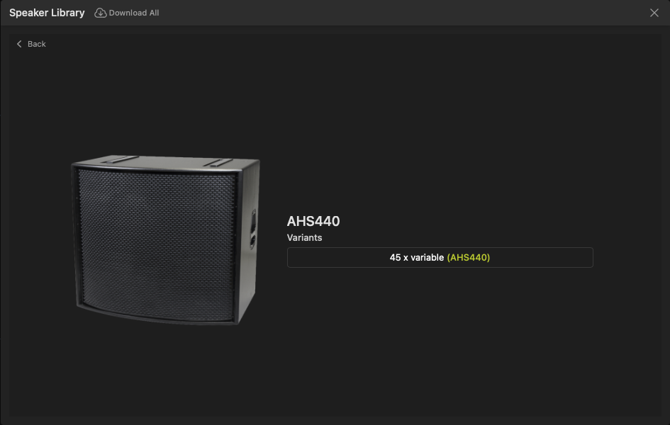
Choose a compatible array loudspeaker to start the array, then choose the variant of that loudspeaker on the next page, such as the AHS440 in the following example:
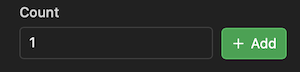
You will then be asked to confirm the quantity of loudspeaker boxes to add to the new array:
Additional array boxes can be added above or below elements using the array properties toolbox.
Array Properties
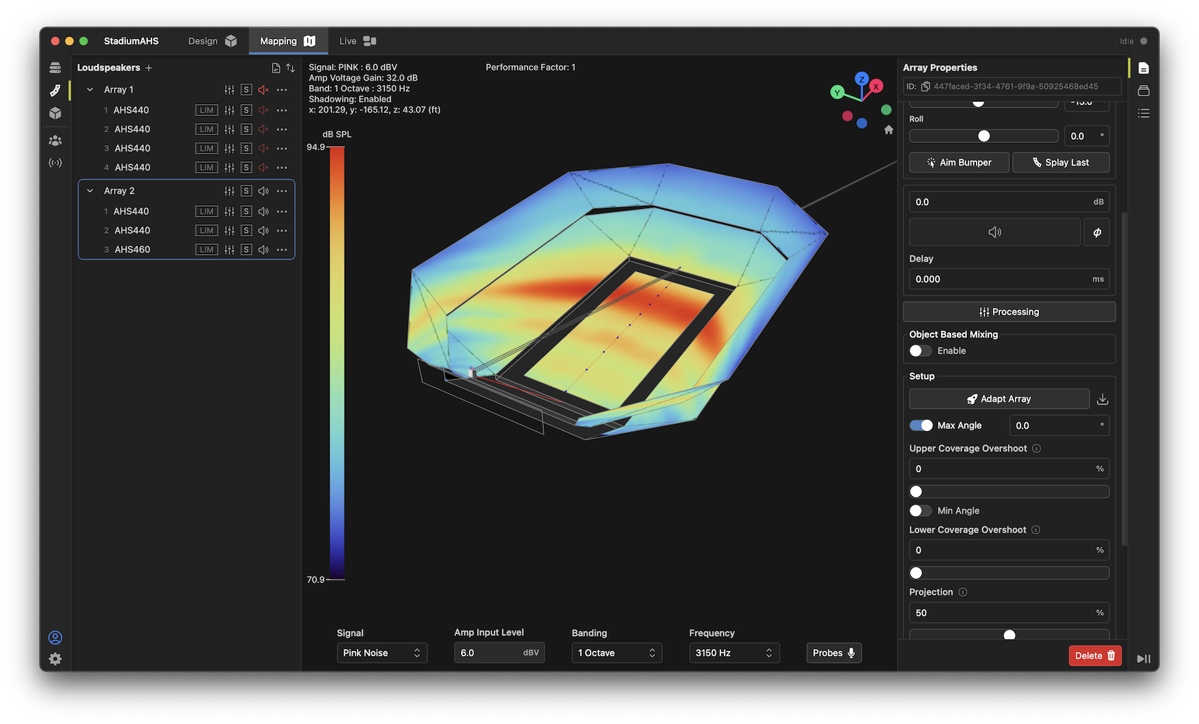
Once a new steered array has been added to the project, you will see the array listed in the Loudspeakers list. Expanding the array in the list will show the individual "member" boxes inside that array. Note that processing, mutes, and solos may be accessed for the entire array as a whole, or for each individual member to assist with design and configuration.
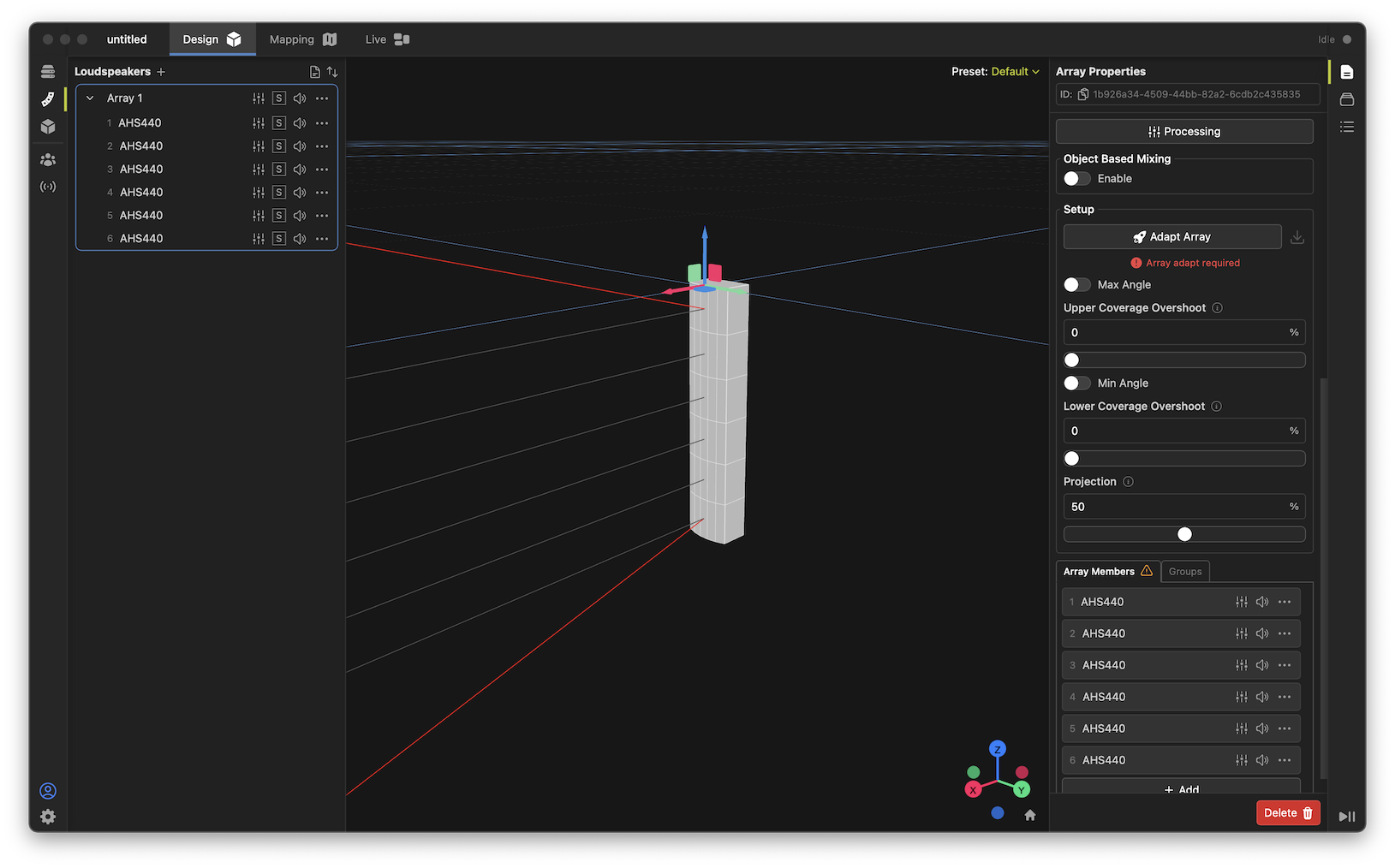
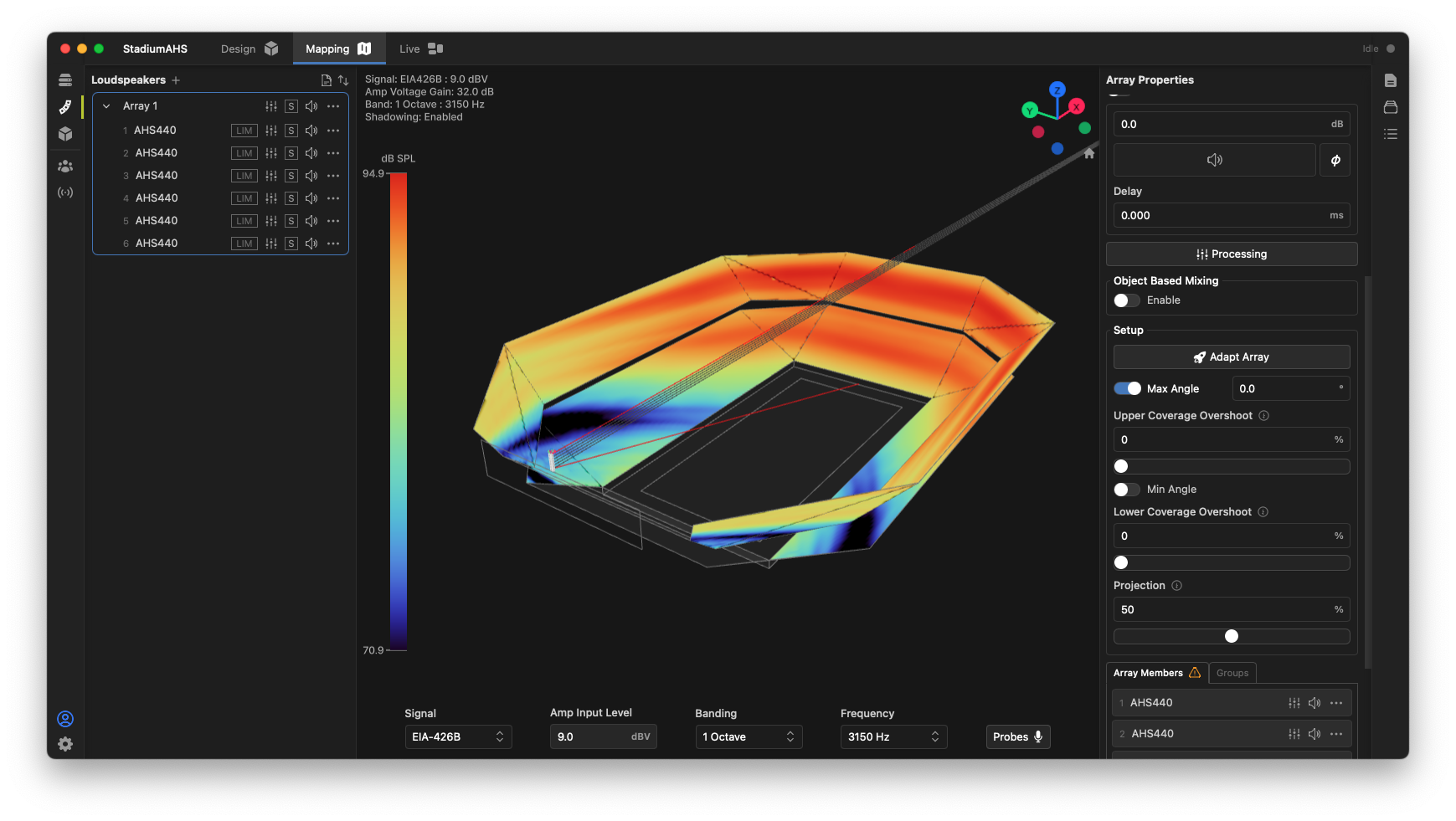
Open the Properties toolbox and select an array in either the Loudspeakers list or in the 3D view. The Array Properties toolbox shows controls necessary to position, aim, and process the array, including:
- Naming, positioning, and overall aiming controls (similar to that of a single loudspeaker box),
- Level, mute, delay and processing controls (similar to that of a single loudspeaker box),
- Setup panel, including "adapt array" button and coverage area modifiers.
- Array Members list for configuration of each member box.
When an array is selected, the 3D view will show positioning controls, the centerline of each member box, and the upper and lower theoretical coverage limits for the current array configuration.
Note the "ground stacked" option is unavailable for AHS arrays, so regardless of the desired installation method, an AHS array must be built starting with the top-most box in the model.
Adding Additional Boxes
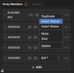
Additional boxes may be added to a steered array by either clicking the Add button at the bottom of the Array Elements list, or by right-clicking an element and selecting Insert Above or Insert Below. Note, the system enforces that the array be built in a "progressive" manner, meaning AHS460-INV on top, AHS440 in the middle, and AHS460 on the bottom.
Adapting a Steered Array
In order to use a steered array in a project, its coverage must be conformed to the audience listening area that it is intended to cover. Fulcrum One makes this process simple and straightforward:
- Add the desired number of array member boxes, and position the array at the desired location in the model.
- You must enable mapping on any audience surfaces that the array will be expected to cover along its axis. Use the
 control to enable model surfaces for mapping if they are not already enabled.
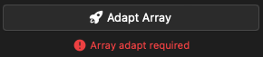
 - Under the Setup controls in the properties toolbox adjust any coverage-modifier parameters desired, and click the Adapt Array button
 .
. - Once the Adapt Array process is complete, the array performance may be evaluated in the Mapping module. Changes may be easily made if modifications are needed.
Setup Controls
Several controls are available to modify the behavior of the steering algorithm for different applications and design requirements. These parameters are available under the Setup section of the array properties window when a steered array is selected. By leaving these parameters at their defaults, a nominal coverage characteristic will be created that attempts to cover any enabled mapping planes inside the physical limits of the array along the centerline (median plane) of the array. These parameters may be used to limit or extend the steering based on other design requirements.
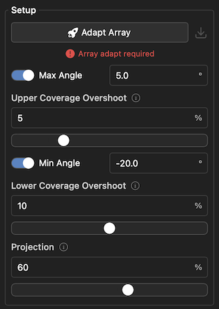
- Adapt Array: Re-conforms the steering of the array to the current setup parameters, enabled mapping planes, and array orientation. This can be pressed at any time.
- Max Angle: Limits the upper coverage angle of the array. This is useful if you don't want to disable specific mapping areas but also don't want to cover them or if you want to cover only part of a mapping area.
- Upper Coverage Overshoot: (0-20%) Extends the upper coverage beyond the intersected mapping area to accommodate more coverage to far seats or other coverage needs that don't align precisely with the median plane of the array. This is a percentage of the overall coverage distance.
- Min Angle: Limits the lower coverage angle of the array. This is useful if you don't want to disable specific mapping areas but also don't want to cover them or if you want to cover only part of a mapping area.
- Lower Coverage Overshoot: (0-20%) Extends the lower coverage beyond the intersected mapping area to accommodate more coverage to near seats, or other coverage needs that don't align precisely with the median plane of the array. This is a percentage of the overall coverage distance.
- Projection: (0-100%) Allows the user to specify a tradeoff between frequency response linearity (projection value of 0%) versus "throw" to long distances (projection value of 100%). 50% is the default.
Real-Time Steering and DSP
When using a steered array with a Fulcrum PA-64 or Venueflex series digital signal processor, array steering may be automatically loaded and implemented in real-time with no further user intervention. In addition, steering changes may be made in real-time by simply varying the coverage settings above and clicking the Adapt Array button: the changes will be immediately reflected in both the mapping display and audible in the venue.
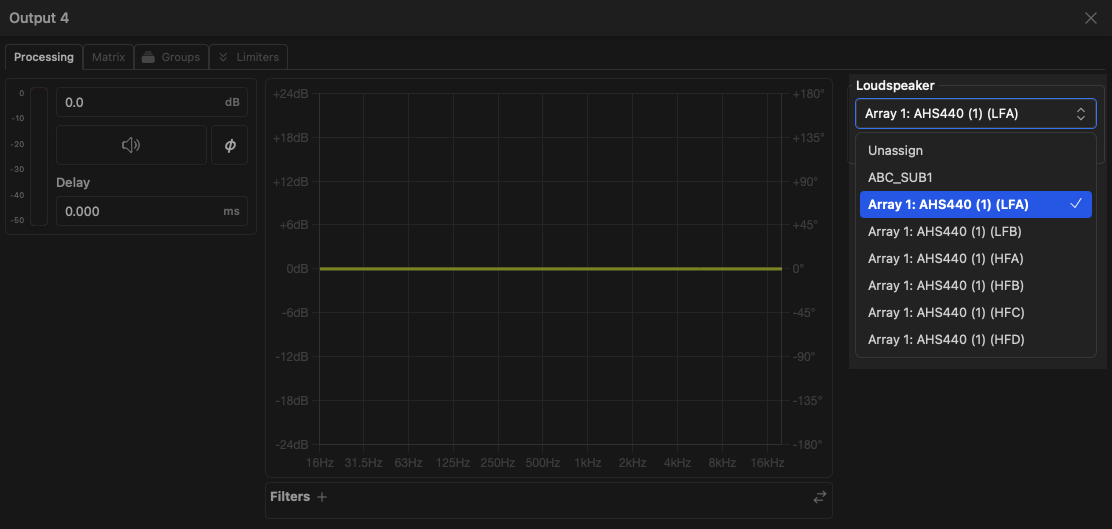
To link a steered array driver channel to a physical DSP output, open the engine's Output channel window and select the desired driver from the Loudspeaker list. Repeat this for all drivers and route those signals to their appropriate amplifier channels.
DSP Settings for External Amplifiers
Calculated steering processing coefficients may be exported for use in stand-alone DSP amplifiers. Contact Fulcrum Acoustic for assistance in loading your design into a third-party amplifier platform.
Exporting Steered Arrays to EASE
Once an array has been adapted, it is possible to export its configuration to EASE for comparative analysis using EASE's XGLC file format. This process has been refined for use with EASE 5.
Exporting Configuration Files from One
-
Once your arrays have been adapted, select any arrays you wish to export in the loudspeaker list. Multiple arrays may be selected and exported simultaneously to a folder of your choosing.
-
Click the
 button beside the Adapt Array button in the Setup section of the array properties toolbox. This will generate an EASE-compatible file in the XGLC format for each array selected.
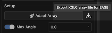
-
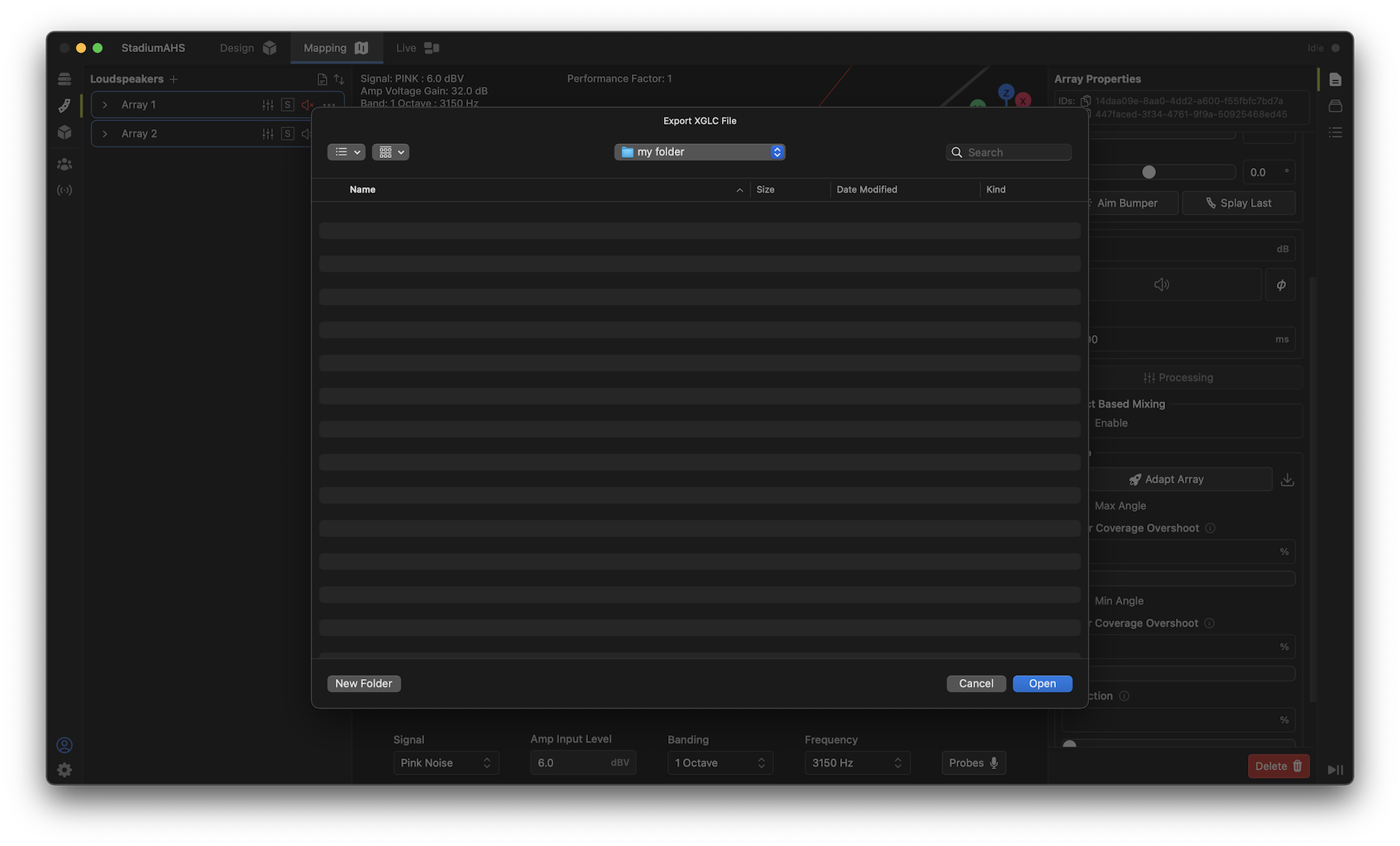
Select the folder to store the generated XGLC files. Filenames are auto-generated based on the name of the arrays in Fulcrum One.
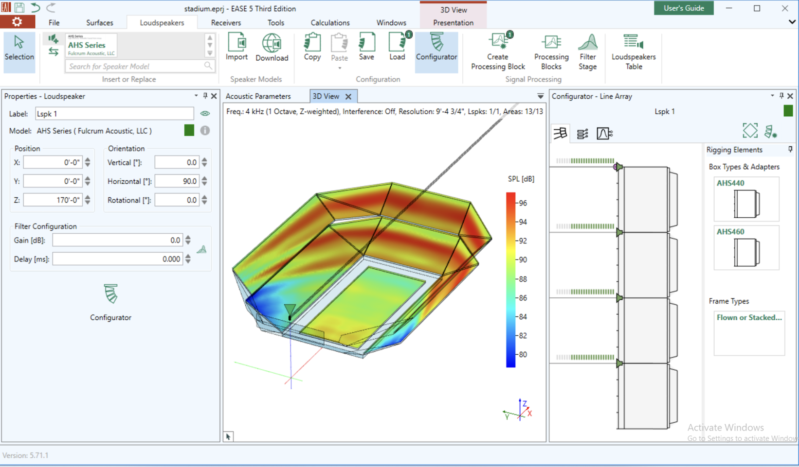
Adding Configured Arrays in EASE
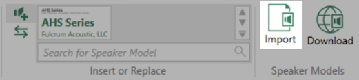
- In EASE, ensure that the AHS Series GLL is loaded and available. If it is not, click the Import button in the Speaker Models section of the Loudspeakers tab to select and load the GLL file.
-
Add an AHS Series array to your project. The relative position and orientation of the array in the EASE project must match the original array in Fulrum One for the steering behavior to be properly aligned with the listening planes.
-
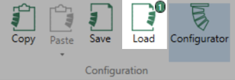
To load the array configuration and steering data for the new array, select the new array in the 3D viewer and then click the Load button in the Configuration section of the Loudspeakers tab in EASE. This will open a file dialog to select the previously exported XGLC file from Fulcrum One.
Repeat the process above for all arrays you wish to import into EASE. Note that minor differences may be present between the performance as simulated in Fulcrum One and what is shown in EASE due to underlying differences in the calculation algorithms used in each software.